
Week 8 - August 29 - September 4
- Victoria Lapp

- Sep 2, 2021
- 3 min read
Updated: Sep 10, 2021
The first task for this week was updating the website. The timeline page was updated to include the proposed timeline from last semester, as well as the actual timeline which we will update as the semester progresses. The budget page was given a similar treatment. The proposed monetary budget is now displayed next to the actual budget that will be updated as items are purchased.
Another task for this week was to create a 3D rendering of our proposed project so that we can have a plan for where/how the sensors will be placed. The figure shown below is the 3D model shown from a downwards angle. From this it can be seen where we removed the handles that originally came attached to the cart. This is where we will attached a flat panel of our own design, upon which the front ultrasonic sensors and IR transceiver will be mounted.

As can be seen in the image, the IR sensors will be mounted to the existing sides of the cart facing straight outwards. The battery will reside on the bottom shelf towards the rear of the cart. Figure 7.2 shows the same model but seen from an upwards angle. This image shows the underside of the bottom shelf where we plan to mount the primary and secondary micro-controller boards as well as the motor drivers. We plan to have these devices in an enclosed box so that they will not become damaged and there is a reduced risk of electrical shock. There will be wires traveling down one of the side support bars to the battery and/or wheels as needed. These wires will be hidden using some electrical tape, again to prevent damage, short-circuits, and/or electrical shock.

It was discovered this week that the motors that were ordered for this project are slightly larger than described by the distributor. This means the motors are slightly larger in diameter than the wheels. Because of this fact, direct drive of the mechanum wheels is no longer possible. After some research and consulting with a mechanical engineer, it was decided that timing belts were the best solution to this project.
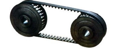
To do this we selected two timing belt pulleys. Our gear ratio is 1:1 so each pulley has the same number of teeth. However, since the mechanum wheels and the motor both have different shaft diameters, we needed to select the appropriate pulley for each device. The mechanum wheels are using a 4mm shaft and the motors have a 5/16" shaft. The timing belt selected is a 6" circle 1/4' wide and will connect both pulleys, allowing the motors to turn the wheels. As long as the pulleys are in line with each other, this configuration gives us the freedom to mount the motors anywhere that we would like to.
Figure 7.3 shows how the pulleys will be connected in order to drive the wheels.
The final task worked on this week was creating a wiring schematic for the primary and secondary board. This schematic is a more concrete version of how the boards will be wired for initial testing. It may be updated as we discover better configurations. The schematic clearly shows each pin and where they will be connected. It also shows how each component within the control module interacts with each other.
Image coming soon


Comments