
Week 8 - August 29 - September 4
- Jesus Diaz-Rivera

- Sep 2, 2021
- 6 min read
Updated: Sep 10, 2021
The IR transceivers were received and verified they could be used to help Red Rover’s following operation through directional operation, or it’s “compass”. The aim is to make the pair of transceivers as visible as possible to each other such that within the 15ft of operation, the Rover can at least know where the user is from the Transceiver they have on their body. When testing the transceiver initially it was thought that it was less accurate than the product description and customer reviews on their website had led us to believe, since whenever both or just one was on they were taking in IR signals from all sources and were reacting to every light they were exposed to. This was not ideal as the pair needed to focus only on each other, but the specifications did explain certain fluorescent lights could also affect the transceiver’s operation. Shielding was then attempted to limit the amount of lighting the IR receivers were exposed to, but this was not helping much as the same issue kept occurring.
After some troubleshooting, two adjustments were made when testing the transceivers that proved to help them find the right signal. On their datasheet it showed the transceivers have different ranges based on what input voltage you use to supply their power. This apparently is a major factor to the pair’s IR detecting as the more voltage they are given, the stringer and more accurate the transceivers became. Initially we gave them only voltage from the controller, which was around 5V, but when connected to a wall outlet supplying approximately 8V, a majority of the issues did not occur, and the transceiver was closer to operating as expected. The testing was first done with several IR remotes to verify it can isolate IR signals as can be seen in the Figures 1 and 2, and one worked more accurately then the other, but this could be that one IR remote, since it is for televisions, had a wider angle of operation than the other and was pinging two receivers on the transceiver at once.

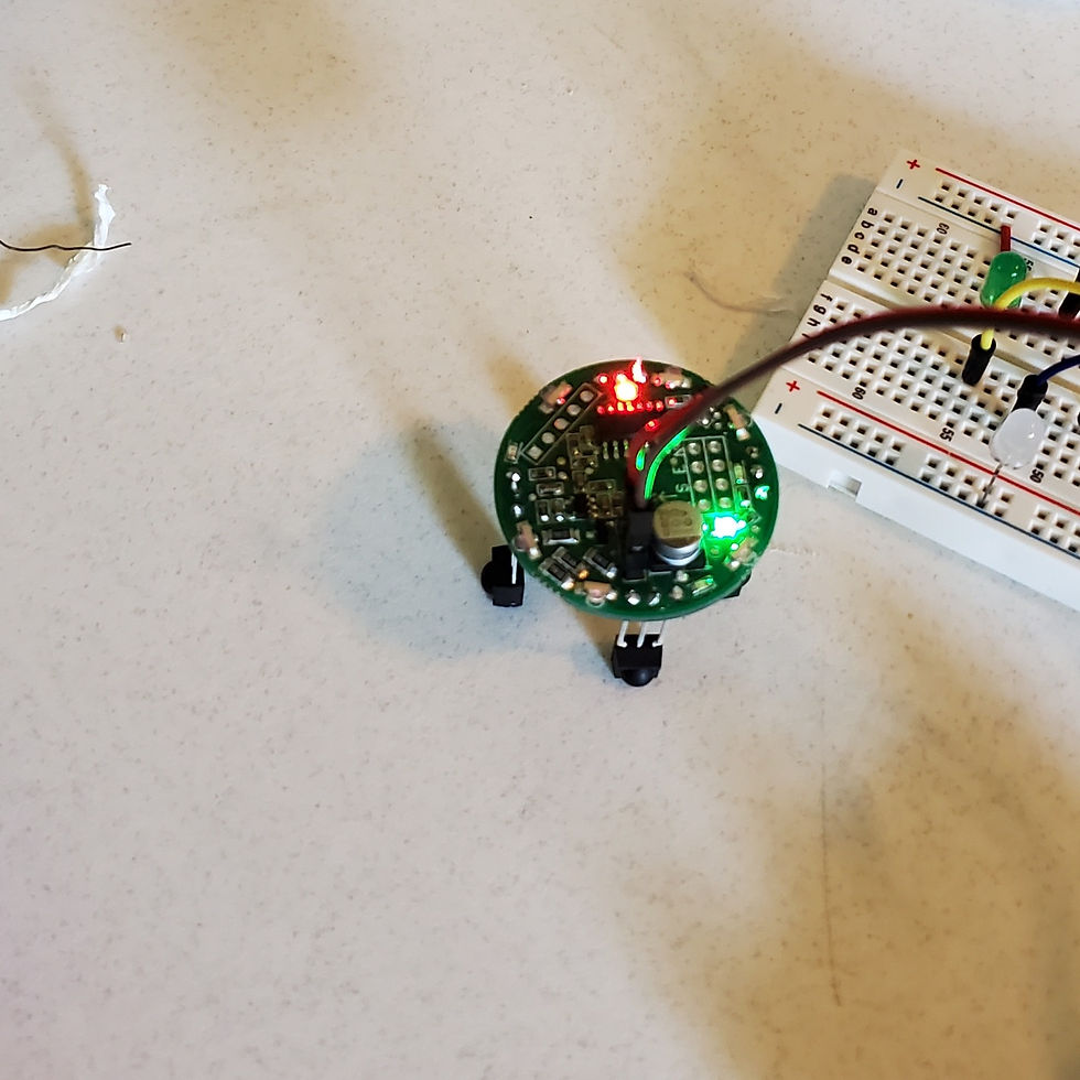
Figure 1 & 2: IR transceivers receiving the same signal with low input voltage (above) and higher input voltage (below).
The other remote used proved that the transceiver can indeed isolate an IR signal and provide the direction it is receiving a signal from. Testing on both active at the same time was then done, and what was found was that if the supplied voltage is closer to the maximum voltage, or 16V, the more accuracy and range the two transceivers will have. This will be fine tuned more when one transceiver is installed on the Rover, and one possible way to further increase the accuracy is to extend each of the transceiver’s receivers to the sides of the cart which can possibly help isolate the sides from one another and help it determine which side the other transceiver is on.
In Figure 3 shown below, an initial illustration of this can be seen, where the transceiver is in the center and the four IR sensors can extend out through wiring to each side.

Figure 3: Potential IR transceiver wire placement
During the weekend, the battery charger that was discussed in the previous meeting was purchased and tested that it can charge the battery while still connected to the terminals and other hardware. It was able to charge the batteries and has the cables to connect to the battery terminals while being in the way of the rest of the hardware. Some methods of how to indicate that the battery needs charging were researched, and one way to do this is to include in the Power module an analog voltmeter that can be made from using the Arduino’s analog ports to detect when the battery voltage has passed below a certain threshold of voltage. This will send back either a signal to the user via app or another method indicating that charging must be done before proper operation can continue. The use should then have plenty of time to charge the Rover by manually driving it to a wall with an outlet. In Figure 4 shown here, terminal blocks were also donated to help wire the different components to the battery at once. A diagram of how this could be achieved can be also seen.


Figure 4 & 5: Terminal blocks (above) and battery connected to battery charger (below)
MIT App inventor
When looking for a method to design an app that would connect to the Rover’s control module, several project app builders were considered and research after the Design proposal was approved. With having very little knowledge on how Android or iOS applications are designed and installed, as well as controlling a phone’s Bluetooth, the group decided to go with a software that would make it easy to develop an app in the software’s environment, and possibly find a way to allow people to get the app on their phone and operate the Rover after a password is input. During the hiatus between summer and fall semesters, the biggest challenge during the initial code building was not only establishing connection between a phone and the Arduino Controller via Bluetooth, but then finding an app that can do that and send different signals from an easy-to-follow menu the user would have access to. LightBlue was a free app that for a while seemed like the only app that could communicate with the Arduino Uno Wi-Fi, as it was designed specifically for BLE devices and the user could specify what type of values one would send to the paired device, whether it was Big/Little Endian, binary, Hex and so forth. It did not, however allow an app or project to be developed within it and could not be called by another app, for example to only be used as a data transmitter. For a while, it was very difficult to find another app that properly connected to the Arduino without losing connection or appearing as an unconnectable device. After much research on project-building apps, MIT app inventor seemed to be the one that allowed all the operation the project needed.
MIT app inventor is described on their website as “an intuitive, visual programming environment that allows everyone – even children – to build fully functional apps for Android and iOS smartphones and tablets.”[] It truly is of all the apps that are designed for open-source development, one of the more accessible and easy to understand. Its code design is a block-diagram style format that allows one to click and drag the command the app would issue to an open area, and the user can decide what action the app will take when the command is executed. For our purpose, the app needed to connect to the BLE (Bluetooth Low Energy) type the Arduino uses and confirm this to the user. It can also give an alert to confirm whether the Control module is connected or disconnected.
Bluetooth connection was established by having the app connect to the Uno’s specific address and only that; not seeing the Bluetooth address will give an error message. Once connected, the buttons displayed on the app will give a different text to send to the Arduino, and respective to the software the Arduino is running, the controller will react to the command accordingly. In the below Figures 5 and 6, it can be seen how the code is designed and how the format for building the app in this software is done. So far, the command to send a character or string only calls that type of data “Text” so it is unclear what data type the Arduino sees it as, but it does differentiate the difference between numbers, so that will be the format commands are given between app and Control module.


Figures 5 & 6: MIT app inventor design blocks and app layout for Red Rover app
To help better understand what types of data is being transmitted between devices, a Model that details what is being sent where was essentially developed for two reasons: to not only have an easier way to explain what values each device would be sending and receiving, but also as a template to help keep track of what is supposed to be transmitted when developing the program. Right now as of this writing there is technically three programs being developed for the whole project: one for the app to communicate to Arduino through Bluetooth, one for the Primary Arduino to register information from the user’s phone and sensor module, and one for the Secondary Arduino to take in directional commands from the Primary Arduino and translate that information tell the connected motor drivers and motors to act accordingly. For example if you follow the table Model, if the user wishes to tell the Rover to move Forward, the up button will be pressed, which will prompt the app to send a “2” to the Uno Wi-Fi, which will then have Pins 1, 2, 3 send a Low, Low, High, respectively, to the Arduino Uno connected to the drivers that control the motors, and the Uno will then issue the proper High and Low’s to have the motors perform the rotations needed to move forward with the connected wheels.

Figure 7: Communication Model


Comments