
Week 15 - October 17-23
- Group Work

- Oct 21, 2021
- 3 min read
The group met on Monday to begin construction of the cart and merging mechanical and electrical components together. We began by mounting the motor mounts and motors to the cart and from there decide where best to put sensors and control module.

While meeting, more final design choices were made about not only the placement of the wheels, but also for sensors and internal electronics for the control and power modules. The Terminal blocks would be placed on the center in between the motors on the bottom shelf to help save space and stay close to the battery. Motor drivers, since they operate a pair of motors at a time, will be put with one next to the front two motors and the other next to the back to motors also on the bottom shelf. As for the control module, it was considered to place the primary and secondary controller as well as the circuit chip of the transceiver underneath the top shelf of the cart to give the best possible elevation for the UNO Wi-Fi to see Bluetooth from the user’s phone as possible and keep sensor wiring to the controllers short as well. So far, the hardware is on plexiglass to keep them together, but the size of it does not work for the small space we have due to the motor taking up space, so resizing of the plexiglass or use of other material was discussed.
The issue with connecting all hardware to power was also investigated on Monday as all components on the top will need to be connected to the battery in some way, and a concept was brought up to connect the wires that need to go from top to bottom shelf through one pipe or tube in between the two cart’s shelves such that all wiring can safely travel through to the respective connections without being exposed. It was planned to begin working on more of the construction of these components in the following weeks.

On Thursday, the team met to continue work on the cart. With the wheel hubs fully assembled and the placement of the motors finalized, we attached the timing belts to the pulley system to test the movement of the wheels. We wanted to check what would happen if the user ignored the low battery alerts. As demonstrated in Video 15.1, the motor shafts can be turned manually while connected to the wheels. This makes the team confident that, should the Rover run out of battery before it has reached a place where it can be charged, the user should be able to manually push the Rover to an outlet without excessive difficulty.
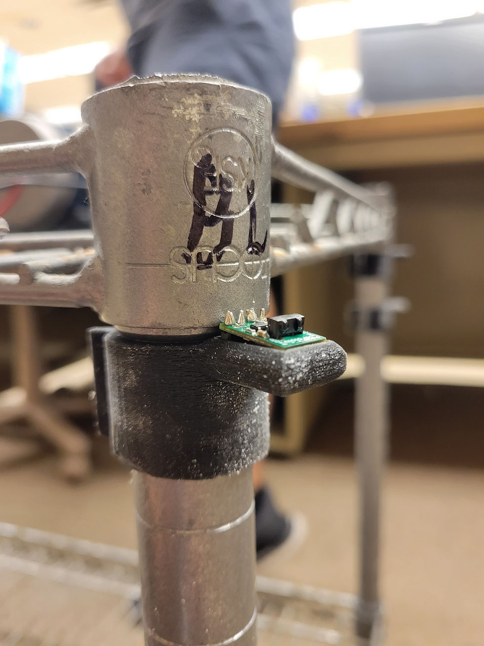
The IR sensor mounts that were designed and printed, while functional, had some issues. The slot for the pins needed to be slightly larger, but even more than that, there was an issue with the print itself. The plastic material had a “melted” look to it. Fearing that this might compromise the integrity of the part, Victoria ran a UV intensity test on the Polyjet 3D printer to see if there was a problem that could be fixed. Video 15.2 shows the UV test.
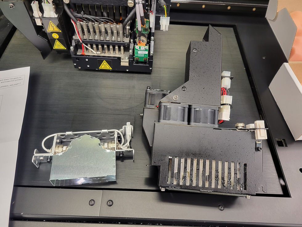
The results of the test showed that one of the UV lamps had burnt out, preventing the print material from curing properly, giving it that melted look. Victoria Replaced the UV lamp as shown in Figure 15.4, and ran a second UV test to ensure that it was working properly before starting to print new IR mounts with the adjustments as mentioned previously.


Comments