
Week 13 - October 3-9
- Victoria Lapp

- Oct 7, 2021
- 2 min read
This week, the mechanical module was assembled. In a previous week it was mentioned that the motors that were purchased were meant designed for direct drive. Because of this, the shaft is shorter and there is a rim around the front of the motor. We believed that we would be able to attach the pulley to the end of the shaft with enough room for the timing belt to clear the rim. However, after some testing, it was decided that it would be safer and more reliable to find a way to attach the pulley lower down on the shaft for better support. To accomplish this, I first assigned each motor a position on the cart (Front left, back right, etc.) and used those positions to determine where the timing belt would come out from the pulley. Then I marked a clearance path (with tolerance just in case). I then used a Dremel tool as shown in Figure 13.1 to cut out that section of the outer rim.

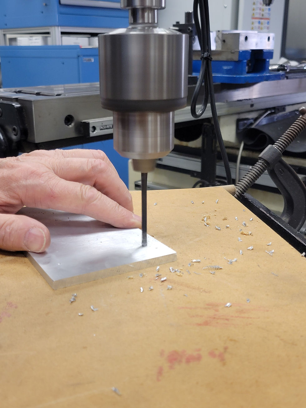
This method worked relatively well, however, while working on the second motor, the mounting screw for the Dremel blade broke. After this I needed to use a different method, and so under the supervision of a professional machinist, I used a knee drill to complete the last three motor modifications. This process is briefly shown in video 13.1 and the finished product is shown in figure 13.2

The next part completed was the mounts for the motors and the mounts for the pillow blocks that will mount the wheel shaft to the cart. These were made from 2 - 6”x12” aluminum sheets that are ¼” thick. First, a horizontal band-saw was used to cut the sheet metal to the desired sizes (see figure 13.3). Next, I used a drill press to drill holes into the sections as shown in figure 13.4 and each hole was then tapped using a hand tapping tool.

After the mounts were completed I moved onto the shafts. To save money, we purchased a 10mm dia 4140 steel alloy rod, and I cut it down to size using the horizontal band-saw. After using the band-saw all of the pieces of metal were sharp/jagged at the edges so for safety I used a sander to sand down the edges so that they were smooth. Figures 13.5-6 show this process.


Once the shafts were cut to size, one more modification needed to be made. The pulleys used require a 10mm shaft, but the mecanum wheels only have an 8mm bore hole. Due to this, the 10mm shaft needed to be turned down, so with the help of a machinist I used a CNC machine to turn down 1.5" of each shaft by 1mm (turning down a 10mm shaft by 1mm equates to an 8mm diameter) as shown in video 13.2.


Comments